Introduction
Commonly used in chemistry for reflux applications, such as Sechelt extraction; provides efficient cooling and condensation; ideal for food, pharmaceutical, and environmental industries; can be used to extract essential oils from plants, determine crude fat content, conduct laboratory-scale refluxing, perform continuous solid extraction with a suitable solvent, and Reflux Condenser more
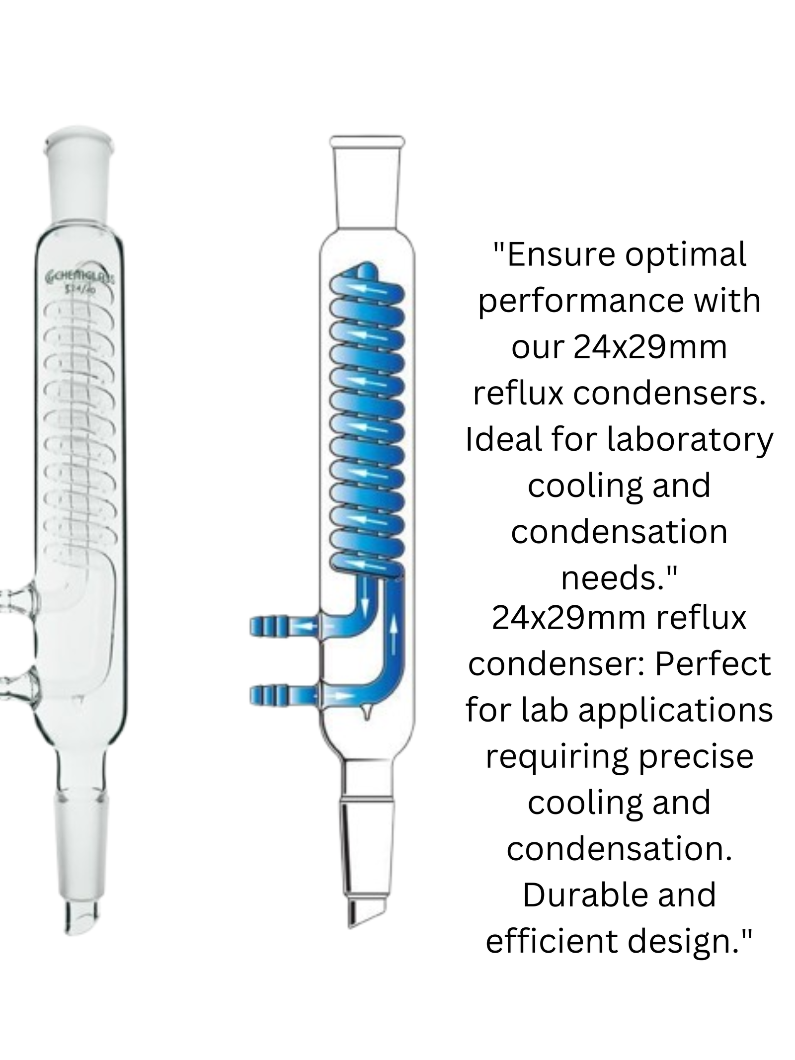
13.7 inch overall height; 9.8 inch in jacket length; the glass Alien condenser is designed with 45/40 ground joint and 0.5 inch diameter tube.
Fits with Labasics Sechelt extractor; maximum withstand temperature 250°C
Made of borosilicate glass; heavy wall and reusable; spherical indentations allow for greater surface area, which increases the effectiveness of the condenser
Warranty: Labasics 1-year limited warranty; if received damaged, please contact us immediately; we will solve it until satisfied
Abstract
Reflux and vent condensers are vertical separators where film condensation occurs. A vapor mixture is supplied at the bottom of the tubes and encounters vertical cold surfaces. A falling film forms and exits from the bottom of the tubes, flowing counter-current to the vapor, but co-current to the coolant on the shell side.
Flooding occurs when the condensate flow moves from a gravity regime to a shear regime. Vapor velocities at or above the flooding velocity will cause the liquid to exit from the top of the tubes rather than from the bottom. The main disadvantage of these condensers is the limited flooding velocity allowed.
Several investigators propose correlations to predict the flooding velocity. In most cases these correlations come from isothermal experiments data, thus the general recommendation of using safety factors of at least 30%. This work compares these correlations to new experimental values of flooding in steam/air vent condensation.
The experimental apparatus is a 3 m long, double-pipe condenser with an internal diameter of 0.028 m. The conclusions presented here will aid the design engineer to understand better the applicability of the discussed correlations in the design of steam/air vent condensers.
1. CONDENSERS
Reflux condenser
A reflux condenser, also called a vent condenser or knockback condenser, is a vertical tube-side condenser in which the vapor flows upward, as indicated in Figure 11.7. These units are typically used when relatively small amounts of light components are to be separated from a vapor mixture.
The heavier components condense and flow downward along the tube walls, while the light components remain in the vapor phase and exit through the vent in the upper header. In distillation applications, they are most often used as internal condensers [4], where the condensate drains back into the top of the distillation column to supply the reflux, or as secondary condensers attached to accumulators (Figure 11.8).
These units have excellent venting characteristics, but the vapor velocity must be kept low to prevent excessive entrainment of condensate and the possibility of flooding. The fluid placement (coolant in shell) entails the same disadvantages as the tube-side downflow condenser.
2. Distillation and Reflux Condensers
Distillation and Reflux heating are common laboratory operations. Distillation becomes necessary when you have to isolate a pure solvent from a mixture of several other solvents based on the differences in their boiling points.
The types of commonly used laboratory distillations have been covered in How to select the optimum laboratory distillation technique. In contrast to distillation the process of reflux in involves heating of the reactants in a flask and through condensation the return of condensed liquid back to the heating flask. This operation is useful in preventing loss of solvent thereby increasing the reaction time over which the flask can be heated.
From a broader perspective, both distillation and reflux may seem the same type of procedures where a solution is boiled and condensed. However, their purposes are entirely different. Where the prior helps with separation of mixture components, the latter one assists in completing a specific reaction. That is why we need to study the use of distillation and reflux condensers independently. Let’s first see how a condenser is use.
3. Parameters and concepts
3.2.3.5 Reflux condenser mode
Reflux condenser mode is a cooling mechanism that could occur in a PWR usually in defined phases of small-break LOCA (SBLOCA) (Pretel, 1997). At a reduced inventory vapor is produced in the core and flows through the hot leg to SG U-tubes where it can condense, fall back to the vessel, and help cool the core.
The secondary side of the SG has to be active (or at least full of water) to provide the condensing capability. Also, during such cooling mode counter current flow occurs in hot leg since vapor flows forward to the SG and liquid flows backward to the vessel.
4. Crude Stabilization
2.3.4 Stabilizer Reflux System
A stabilizer reflux system consists of a reflux condenser, reflux accumulator, and reflux pumps. The system is designed to operate at a temperature necessary to condense a portion of the vapors leaving the top of the stabilizer.
The temperature range can be determined by calculating the overhead vapor’s dew-point temperature. The heat duty required is determined by the amount of reflux required.
The selection of the type of exchanger for the reflux condenser depends upon the design temperature required to condense the reflux.
The lower the operating pressure of the stabilizer, the lower the temperature required for condensing the reflux will be. In most installations, air-cooled exchangers may be used. Other instances may require refrigeration and a shell-and-tube-type exchanger will be used.
5. Equipment and Buildings
Reflux Vessels
The vapor stream coming from the overhead of a distillation column is condensed and the resulting liquid is collected in a reflux drum so that fluctuations in flow can be ironed out (the drum will typically have a residence time of around 5–10 min). Because the condenser/reflux system removes heat from the system it will generally be kept in operation during the course of an emergency.
Therefore the reflux vessel and its associated pumps and piping should be protected against external fire, either with fireproofing or water sprays.
6. Dehydration
7.4.3.3 Reflux Condenser
From the glycol gas contactor, the cool wet glycol passes through a coil (reflux condenser) in the top of the rebuilder still column. The coil cools the vapors leaving the still column and condenses the glycol vapors to liquid.
The glycol liquid droplets gravitate back down the still column to the reconcentrator. The water remains as a vapor and continues out the top of the still column. The cooling coil is commonly called the reflux condenser.
7. Understanding the air cooled reflux system
chemical laboratory have been the trigger for the development of new reflux condensers without water cooling. With the Fin denser™, Heidolph offers an efficient, air cooled reflux system, too.
The Heidolph ‘Reflux Condenser Buyer’s Guide’ answers the most important questions you may have. For all other matters, the Heidolph Customer Support will be glad to provide advice.
1. Why refluxing?
Refluxing is one of the most common working methods for organic synthesis. Many chemical reactions only take place under heat or are accelerated by an increased re – action temperature. Reflux condensers are used to prevent the solvent of a reaction mixture from evaporating even when it is heated for extended periods of time.
2. Air cooled or water cooled. What is the difference?
The refluxing principle is as simple as it is ingenious: The boiling vapor from the solution in the flask rises vertically upwards in the glass column, condenses on the cooling surfaces and drops back into the flask as liquid condensate. Cooling inside a reflux condenser takes place according to the heat exchanger principle. The following applies for the cooling surfaces: the larger the surface, the better the cooling behavior.
Water cooled: : In a predominant number of cases, tap water is used as coolant. Like a water sheath, it flows around the reflux column on the inside of which the boiling vapor rises. Convexities on the inner side walls of the column or cooling coils enlarge the cooling surface. (Fig. 1 Functional prin – ciple of a water cooled reflux condenser)
Air cooled: Reflux condensers with air course available in different versions. In low-priced systems, heat exchange with the ambient air takes place only on the outer surfaces of the glass column. Thus, the column must be accordingly high to be able to dissipate heat to the environ – mint. The much more elaborately designed reflux condenser system Fin denser™ is equipped with a finned aluminum jacket, which multiplies the heat exchanger surface in a compact way.
3. Essential: accurate temperature control.
Many tests have shown that the Fin denser™ works with particular efficiency if the temperature is accurately controlled. The control temperature set at the hotplate should be 10 – 15 °C / 50 – 59 °F above the boiling point of the solvent used. If it is too high or if it strongly fluctuates, the solvent can boil over and the sample can be damaged.
4. Suitable for almost all ambient conditions.
The higher the ambient temperature, the worse the performance. Compared to water cooled models, the ambient temperature plays an important role in air cooled reflux condensers. For this reason and of course also for safety reasons, we generally recommend performing refluxing in the fume hood. This ensures reproducibility and the room temperature is no longer an issue.
5. The best is to test: solvent volume.
The volume too is a determining factor for solvent loss during refluxing. Traditional, air cooled reflux condensers are in many cases not efficient enough for larger volumes. At high volatility, too much, if not all, of the solvent is lost relatively quickly. Even the air cooled Fin denser™ – despite its significantly higher cooling capacity – sometimes reaches its limits. To be on the safe side, carry out a test under real conditions with highly volatile solvents like ether before the actual test; always work in the fume hood while doing so.
6. Good price/performance ratio.
Simple reflux condensers can already be bought at little money. However, you should always put the running expenses for water and cooling energy into relation to the costs of acquisition. Especially the safety aspect should not be underestimated. In the event of flooding, the dam.
7. Water consumption and co – oiling costs.
Extrapolated, an average of 150 liters of water flow through a water cooled reflux condenser per hour (Fig. 2 Diagram Water consumption in comparison). Fortunately, many laboratories have installed reticule – ting chillers or central water recalculating systems to reduce the enormous water consumption during refluxing. However, even cooling the coolant has a negative impact on the energy balance.
8. Safety in the laboratory has many facets.
If you have ever witnessed how fast a hose can come off a water cooled reflux con – denser and the immense damage caused by such a flooding in a laboratory building you will appreciate an air cooled laboratory condenser as a true alternative. In the worst case, laboratory equipment worth thousands of dollars can be destroyed overnight.
After all, roughly 2.5 liters per minute are flowing through a water cooled reflux system. In addition, the lack of any tubing – as in air cooled reflux condensers – means that there is no risk of the tubing coming into contact with hotplates (leakages) and furthermore entails a simple setup and less space that is required in the fume hood.
8. The Integration of Process Design and Control
2 EFFECT OF A DESIGN DECISION
To illustrate the effect a seemingly innocent design decision can have on control, consider a partial condenser at the top of a distillation column. A simple and cheap design alternative is to mount the condenser directly on top of the column, what is called a dephlegmator (Fig. 1). The vapor from the column passes up through the tubes, where some of it condenses from contact with coolant on the shell side.
The condensed liquid falls back down the tubes into the column as reflux while the remaining uncondensed vapor leaves via the overhead product line. An alternative design is to mount the condenser external from the column (Fig. 2).
The overhead column vapor passes into the tubes of the condenser, where part is condensed with coolant on the shell side. The condensed liquid collects in the reflux drum, from which it is pumped or flows by gravity back to the column as reflux. The uncondensed vapor leaves as product.
Crude Stabilization
2.2.11 Crude Stabilizer with Reflux
A typical crude stabilization system with reflux and a feed/bottom heat exchanger is shown schematically in Figure 2.5. In this application the column’s top temperature is controlled through cooling and condensing part of the hydrocarbon vapors leaving the tower and pumping the resulting liquids back to the tower. This replaces the cold-feed to the previous stabilizer and allows better control of the overhead product and, consequently, slightly higher recovery of the heavier ends.
A heat balance around the tower is part of the design. The heat leaves the tower in the form of vapors out the top, and the liquid bottom product has to be balanced by the heat entering in the feed and the rebuilder. Naturally, if the column has a reflux, this amount of heat has to be added to the column balance.
A properly designed and operated stabilizer can meet a desired crude oil vapor pressure and results in product recovery superior to that of a typical multi-stage separator system, but the initial investment and operation costs of a stabilizer will be higher.
9. CONDENSERS
1. 11.2 Types of Condensers
Most condensers used in the chemical process industries are shell-and-tube exchangers or air-cooled exchangers. In the latter, the condensing vapor flows inside a bank of finned tubes and ambient air blown across the tubes by fans serves as the coolant. Other types of equipment, such as double-pipe exchangers, plate-and-frame exchangers, and direct contact condensers are less frequently used. In direct contact condensing, the coolant is sprayed directly into the condensing vapor.
This method is sometimes used for intermediate heat removal from distillation and absorption columns by means of pump rounds. While direct contacting provides a high rate of heat transfer with Low pressure drop, it is obviously limited to applications in which mixing of coolant and condensate is permissible.
2. 11.2.1 Horizontal shell-side condenser
Most large condensers in the process industries are oriented horizontally in order to minimize the cost of support structures and facilitate maintenance operations. The condensing vapor is often an organic compound or mixture and the coolant is most often water, a combination that favors the use of finned tubes. Therefore, the condensing vapor is most frequently placed in the shell (the finned side) and the cooling water, which is usually more prone to fouling, flows in the tubes.
3. 11.2.2 Horizontal tube-side condenser
occurs in kettle and horizontal thermosyphon reboilers when the heating medium is steam or a condensing process stream. Multiple tube-side passes (usually two) can be used as well as the single pass shown in Figure 11.4. Two-phase flow This configuration, illustrated in Figure 11.4, is sometimes used to condense high-pressure or corrosive vapors. It also regimes are an important consideration in design of these units since flow instabilities can cause operational problems [1].
4. 11.2.3 Vertical shell-side condenser
This configuration, illustrated in Figure 11.5, is most commonly encountered in vertical thermosyphon rebuilders when the heating medium is steam or a condensing process stream. It is not widely used for condensing, per se. Vapor enters at the top of the shell and flows downward along with the condensate, which is removed at the bottom. The vent is placed near the bottom of the shell, but above the condensate level. The tube bundle may be either baffled or snaffled.
5. 11.2.4 Vertical tube-side down flow condenser
This configuration (Figure 11.6) is often used in the chemical industry [4]. It consists of an E-shell with either a floating head or fixed tube sheets. The lower head is over-sized to accommodate the condensate and a vent for non-condensable. The upper tube sheet is also provided with a vent to prevent any non-condensable gas, such as air, that may enter with the coolant from accumulating in the space between the tube sheet and the upper coolant nozzle.
6. 11.2.5 Reflux condenser
A reflux condenser, also called a vent condenser or knockback condenser, is a vertical tube-side condenser in which the vapor flows upward, as indicated in Figure 11.7. These units are typically used when relatively small amounts of light components are to be separated from a vapor mixture. The heavier components condense and flow downward along the tube walls, while the light components remain in the vapor phase and exit through the vent in the upper header.
In distillation applications they are most often used as internal condensers [4], where the condensate drains back into the top of the distillation column to supply the reflux, or as secondary condensers attached to accumulators (Figure 11.8). These units have excellent venting characteristics,
10.The Integration of Process Design and Control
2 EFFECT OF A DESIGN DECISION
To illustrate the effect a seemingly innocent design decision can have on control, consider a partial condenser at the top of a distillation column. A simple and cheap design alternative is to mount the condenser directly on top of the column, what is called a dephlegmator (Fig. 1). The vapor from the column passes up through the tubes, where some of it condenses from contact with coolant on the shell side.
The condensed liquid falls back down the tubes into the column as reflux while the remaining uncondensed vapor leaves via the overhead product line. An alternative design is to mount the condenser external from the column (Fig. 2). The overhead column vapor passes into the tubes of the condenser, where part is condensed with coolant on the shell side.
The condensed liquid collects in the reflux drum, from which it is pumped or flows by gravity back to the column as reflux. The uncondensed vapor leaves as product.
Question
1. What is the reflux of a condenser?
Reflux involves heating the chemical reaction for a specific amount of time, while continually cooling the vapor produced back into liquid form, using a condenser. The vapors produced above the reaction continually undergo condensation, returning to the flask as a condensate.
2. What is the principle of reflux extraction?
Reflux extraction is a solid–liquid extraction process at a constant temperature with repeatable solvent evaporation and condensation for a particular period of time without the loss of solvent. The system is widely used in herbal industries as it is efficient, easy to operate and cost effective (Wang et al., 2013).
3. What is type of condenser?
The major types of condensers used are (1) water-cooled, (2) air-cooled, and (3) evaporative. In evaporative condensers, both air and water are used. Three common types of water-cooled condensers are (1) double pipe, (2) shell and tube (as shown in Fig. 6.9), and (3) shell and coil.
4. How to wash a reflux condenser?
Soak in citric acid & hot water for an hour (half a cup or so) after a good soak in Dawn with hot water. Rinse thoroughly with ( you guessed it) hot water.30-Mar-2022.
5. What is the role of reflux condenser in today’s experiment?
The use of a reflux condenser avoids loss of reactants in a chemical reaction; therefore, the actual yield of products is obtained. Therefore, a reflux condenser is used to avoid wastage of chemical reactants during the reaction.